Datums & Datum Reference Frames
What is a Datum?
A datum is a theoretically exact point, axis, or plane from which measurements are made. Think of it as the "origin" or reference point for all location and orientation tolerances.
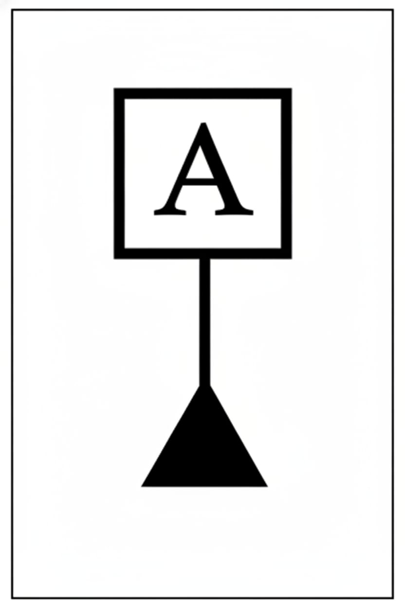
On engineering drawings, datums are identified by letters (A, B, C, etc.) inside a square frame:
    ┌───┐
────┤ A ├────
    └───┘
Theoretical vs. Physical
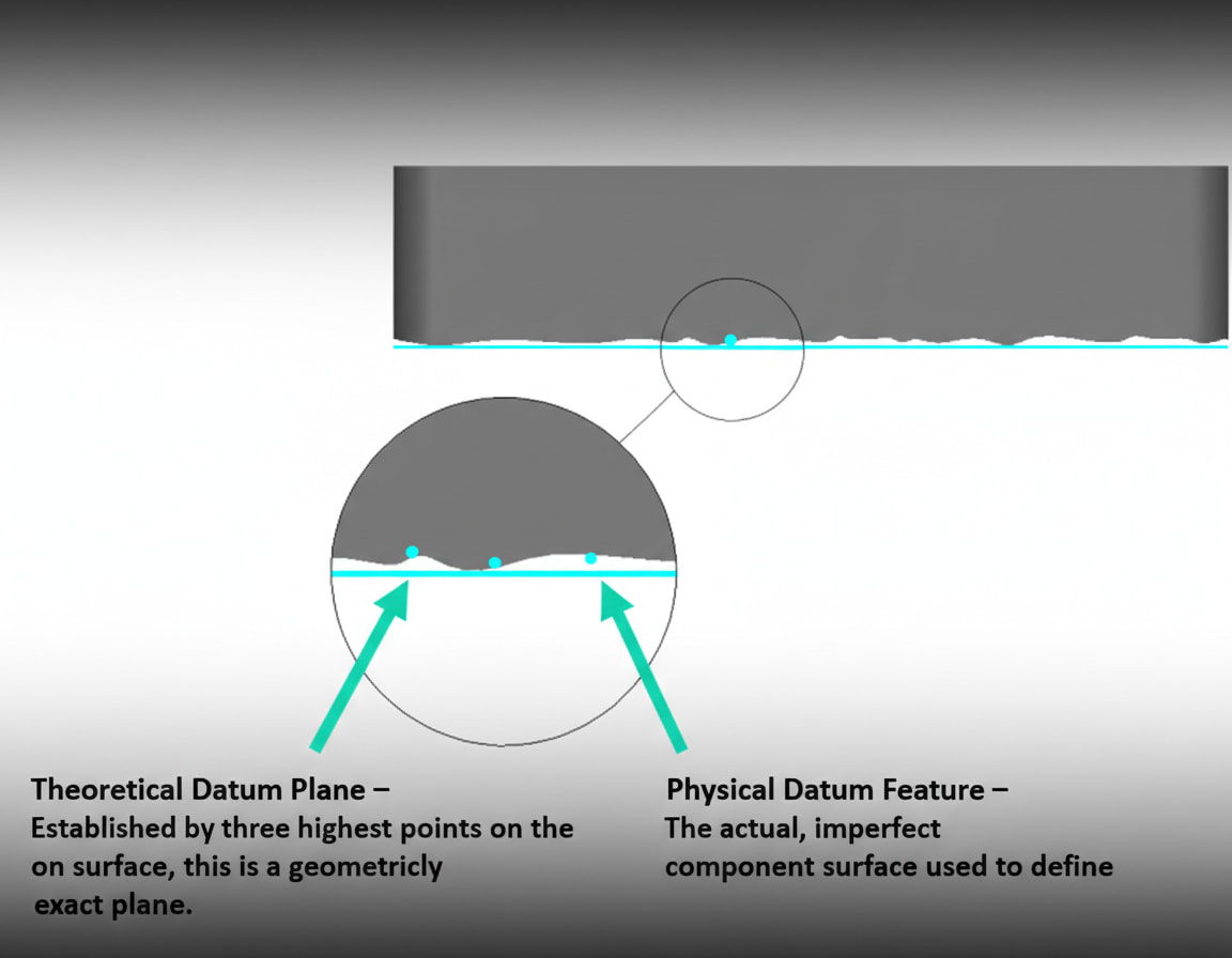
It's crucial to understand:
Sponsored
175+ hours of industry projects & 12 IIT faculty sessions
Master CATIA, NX, LS-DYNA, HyperMesh and more
- Datum = Theoretical (perfect, exact)
- Datum Feature = Physical (the actual surface on the part)
- Datum Simulator = Inspection equipment (surface plate, gage pin, etc.)
When a part sits on a surface plate, the plate simulates the theoretical datum plane.
The Datum Reference Frame (DRF)
A complete Datum Reference Frame consists of three mutually perpendicular planes that establish a coordinate system:
        │ Datum B (Secondary)
        │
        │
────────┼──────── Datum A (Primary)
       ╱
      ╱
     ╱ Datum C (Tertiary)
The DRF constrains all six degrees of freedom:
Sponsored
3,000+ engineers placed at top companies in 2024
Mahindra, Bosch, TATA ELXSI, Capgemini and more
- 3 translational (X, Y, Z movement)
- 3 rotational (pitch, roll, yaw)
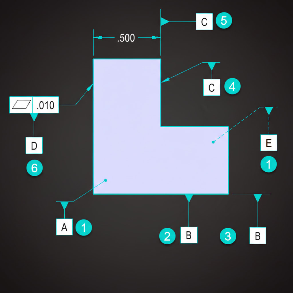
Datum Precedence: A-B-C Order Matters!
The order of datums in the FCF is critical:
| Datum | Role | Degrees Constrained |
|---|
| Primary (A) | First contact | 3 (one plane) |
| Secondary (B) | Second contact | 2 (one line) |
| Tertiary (C) | Third contact | 1 (one point) |
┌──────────┬──────────┬────────┬────────┬────────┐
│ ⊕        │ ⌀ 0.25   │ A      │ B      │ C      │
└──────────┴──────────┴────────┴────────┴────────┘
This reads: Position relative to A (primary), then B (secondary), then C (tertiary).
Changing the order changes the meaning completely!
Sponsored
Get up to ₹60,000 off with Founder's Scholarship
Only 42 seats left for the April batch
Establishing Datums from Features
Flat Surface → Datum Plane
A flat surface establishes a datum plane. The part contacts the datum simulator at its three highest points.
Cylindrical Feature → Datum Axis
A hole or shaft establishes a datum axis running through its center.
Width Feature → Datum Center Plane
Two parallel surfaces establish a datum center plane.
Datum Targets
For irregular or flexible parts, datum targets specify exact points, lines, or areas for contact:
| Symbol | Meaning |
|---|
| A1 | Datum A, target point 1 |
| A2 | Datum A, target point 2 |
| A3 | Datum A, target point 3 |
Three target points establish a plane (like a tripod).
Common Datum Scenarios
Scenario 1: Flat Part
- A = Bottom surface (primary plane)
- B = Long edge (secondary, constrains rotation)
- C = Short edge (tertiary, final constraint)
Scenario 2: Cylindrical Part
- A = End face (primary plane)
- B = Outer diameter (secondary axis)
Scenario 3: Machined Block
- A = Large flat surface (primary)
- B = Perpendicular surface (secondary)
- C = Third perpendicular surface (tertiary)
Key Takeaways
- Datums are theoretical reference points, axes, or planes
- The Datum Reference Frame establishes a coordinate system
- Datum order (A-B-C) matters—it defines constraint precedence
- Primary constrains 3 DOF, secondary 2 DOF, tertiary 1 DOF
- Datum targets specify contact points for irregular parts
---
Next Lesson: Form Controls - controlling the shape of individual features.


