Location Controls
What are Location Controls?
Location controls define where a feature must be located relative to a datum reference frame. They control the position of features like holes, pins, slots, and bosses.The primary location control is:
| Symbol | Name | Controls |
|---|---|---|
| ⊕ | Position | Location of feature's axis or center plane |
Note: Concentricity and Symmetry were deprecated in ASME Y14.5-2018 in favor of Position with appropriate modifiers.
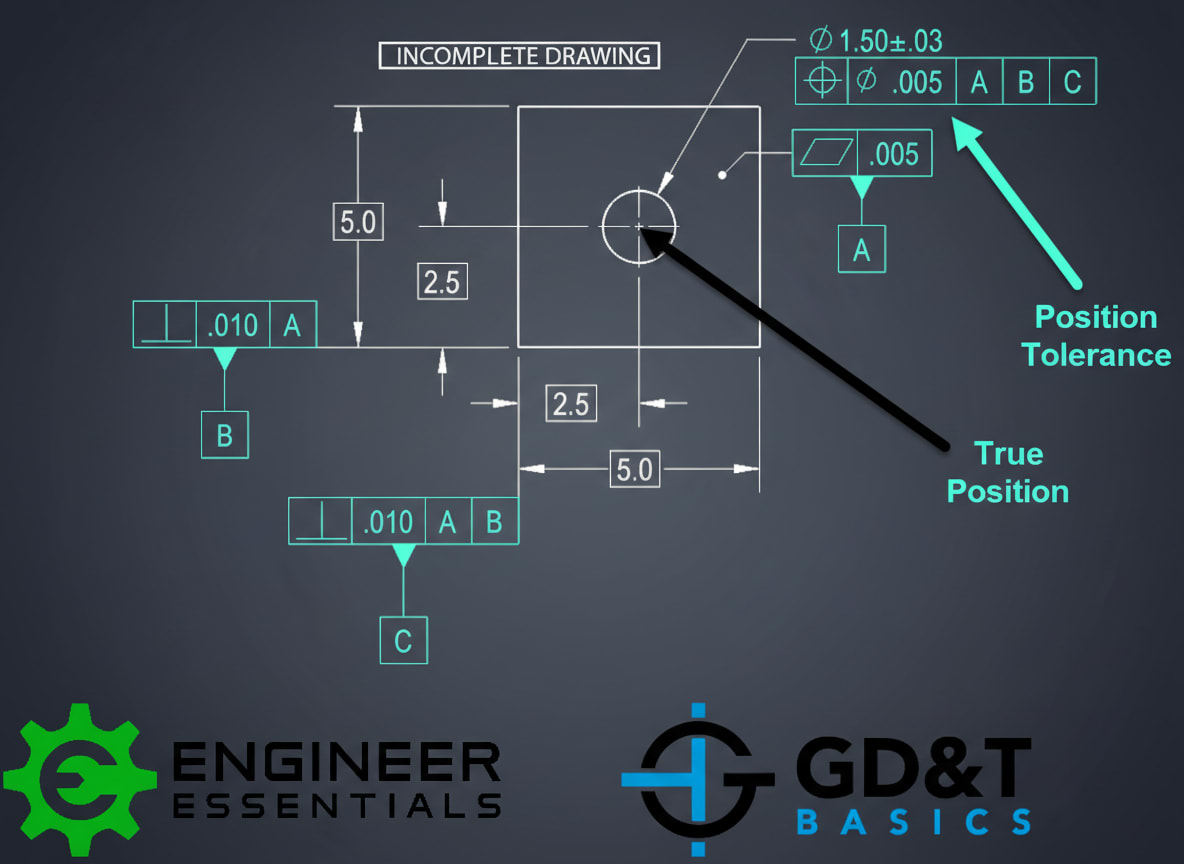
True Position
True position is the theoretically exact location of a feature as defined by basic dimensions from datums.Basic dimensions are shown in boxes and have no tolerance:
┌────┐ ┌────┐
│ 50 │ │ 30 │
└────┘ └────┘
│ │
▼ ▼
════════╬════════════════ Datum B
║
║ ⊙ ← Hole's true position
║
════════╬════════════════ Datum A
Position Tolerance
The position tolerance defines a cylindrical (or planar) zone within which the feature's axis must lie:
FCF: ┌───┬────────────┬────────┬────────┬────────┐
│ ⊕ │ ⌀ 0.25 (M) │ A │ B │ C │
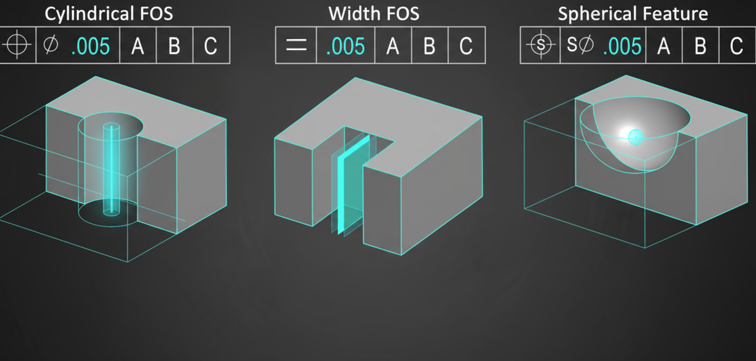
└───┴────────────┴────────┴────────┴────────┘
Reading: "Position tolerance of 0.25 diameter at MMC, relative to datums A (primary), B (secondary), C (tertiary)."
The Cylindrical Tolerance Zone
For holes and pins, position creates a cylindrical zone:
╭─────╮
True │ ⌀ │ ⌀ 0.25 tolerance zone
Position ──► │ ○ │
╰─────╯
│
Actual axis must lie within this cylinder
Calculating Position Deviation
The position deviation formula:
Position Deviation = 2 × √(ΔX² + ΔY²)
Where:
- ΔX = deviation from true position in X
- ΔY = deviation from true position in Y
- Hole center is 0.08mm off in X
- Hole center is 0.06mm off in Y
- Position deviation = 2 × √(0.08² + 0.06²) = 2 × 0.10 = 0.20mm
If tolerance is ⌀ 0.25, the part passes (0.20 < 0.25).
Bonus Tolerance (MMC/LMC)
When (M) is specified, you get bonus tolerance as the feature departs from MMC:
For a Hole (Internal Feature)
- MMC = Smallest hole (most material)
- LMC = Largest hole (least material)
Example:
Hole size: ⌀ 10.0 ± 0.2
MMC = 9.8mm (smallest)
LMC = 10.2mm (largest)
Position: ⌀ 0.25 (M)
If actual hole = 10.0mm:
Bonus = 10.0 - 9.8 = 0.2mm
Total position tolerance = 0.25 + 0.2 = 0.45mm
Bonus Tolerance Table
| Actual Hole Size | Bonus | Total Position Tolerance |
|---|---|---|
| 9.8 (MMC) | 0 | 0.25 |
| 9.9 | 0.1 | 0.35 |
| 10.0 | 0.2 | 0.45 |
| 10.1 | 0.3 | 0.55 |
| 10.2 (LMC) | 0.4 | 0.65 |
Position for Hole Patterns
Position is commonly used for bolt hole patterns:
○───────○
│ │
│ ⊕ │ Basic dimensions locate pattern
│ │
○───────○
FCF: ┌───┬────────────┬────────┬────────┐
│ ⊕ │ ⌀ 0.50 (M) │ A │ B │
└───┴────────────┴────────┴────────┘
All holes in the pattern must meet the position tolerance.
Composite Position Tolerance
For patterns requiring both pattern location AND hole-to-hole relationship:
┌───┬────────────┬────────┬────────┬────────┐
│ ⊕ │ ⌀ 0.50 (M) │ A │ B │ C │ ← Pattern to datums
├───┼────────────┼────────┴────────┴────────┤
│ ⊕ │ ⌀ 0.15 (M) │ │ ← Hole-to-hole
└───┴────────────┴──────────────────────────┘
- Upper segment: Pattern location relative to datums (0.50)
- Lower segment: Feature-to-feature relationship (0.15)
Position vs. Concentricity
| Characteristic | Position | Concentricity (Deprecated) |
|---|---|---|
| What it controls | Axis location | Mass center location |
| Zone shape | Cylindrical | Cylindrical |
| Modifiers | Allows MMC/LMC | RFS only |
| Inspection | Simple | Complex |
Key Takeaways
- Position controls feature location relative to datum reference frame
- Basic dimensions define true position (shown in boxes)
- Position tolerance creates a cylindrical zone for axes
- MMC modifier provides bonus tolerance as feature departs from MMC
- Composite position controls both pattern location and feature-to-feature
- Position replaces the deprecated Concentricity and Symmetry
---
Next Lesson: Profile Controls - controlling complex shapes and surfaces.