Common Defects & Troubleshooting
Overview
Injection molding defects can be categorized by root cause:
- Flow-related — Short shots, jetting, flow lines
- Thermal — Burn marks, degradation, cold slugs
- Pressure-related — Flash, sink marks, voids
- Cooling-related — Warpage, shrinkage variation
- Mechanical — Ejector marks, drag marks
Sink Marks
 Description: Depressions on the surface, typically above thick sections like ribs or bosses.
Root Cause: Insufficient material in thick sections during cooling. As the core solidifies and shrinks, it pulls the surface inward.
Solutions:
Description: Depressions on the surface, typically above thick sections like ribs or bosses.
Root Cause: Insufficient material in thick sections during cooling. As the core solidifies and shrinks, it pulls the surface inward.
Solutions:
| Category | Action |
|---|---|
| Design | Reduce wall thickness; rib = 50-60% of wall |
| Design | Core out thick sections |
| Process | Increase pack pressure |
| Process | Increase pack/hold time |
| Process | Lower melt temperature (less shrinkage) |
| Tooling | Add cooling to thick areas |
Warpage
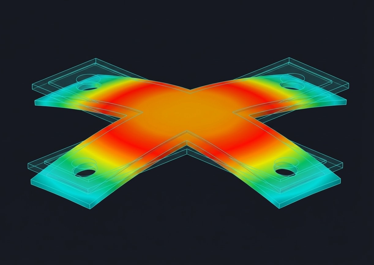 Description: Part distortion—bowing, twisting, or curling after ejection.
Root Cause: Uneven shrinkage caused by:
Description: Part distortion—bowing, twisting, or curling after ejection.
Root Cause: Uneven shrinkage caused by:
- Non-uniform cooling
- Differential crystallization
- Residual stress from filling
- Fiber orientation (reinforced materials)
| Category | Action |
|---|---|
| Design | Uniform wall thickness |
| Design | Symmetric geometry |
| Process | Balance mold temperatures (core vs. cavity) |
| Process | Increase cooling time |
| Process | Reduce injection speed (less orientation) |
| Tooling | Improve cooling uniformity |
| Tooling | Conformal cooling for complex parts |
Flash
 Description: Thin excess material at the parting line or around inserts.
Root Cause: Plastic escaping between mold faces due to:
Description: Thin excess material at the parting line or around inserts.
Root Cause: Plastic escaping between mold faces due to:
- Excessive injection/pack pressure
- Insufficient clamp force
- Mold damage or wear
- Poor venting (pressure builds, forces parting)
| Category | Action |
|---|---|
| Process | Reduce pack pressure |
| Process | Reduce injection speed |
| Process | Lower melt temperature |
| Process | Verify clamp force adequate |
| Tooling | Repair parting line |
| Tooling | Check for mold wear |
| Machine | Verify platen parallelism |
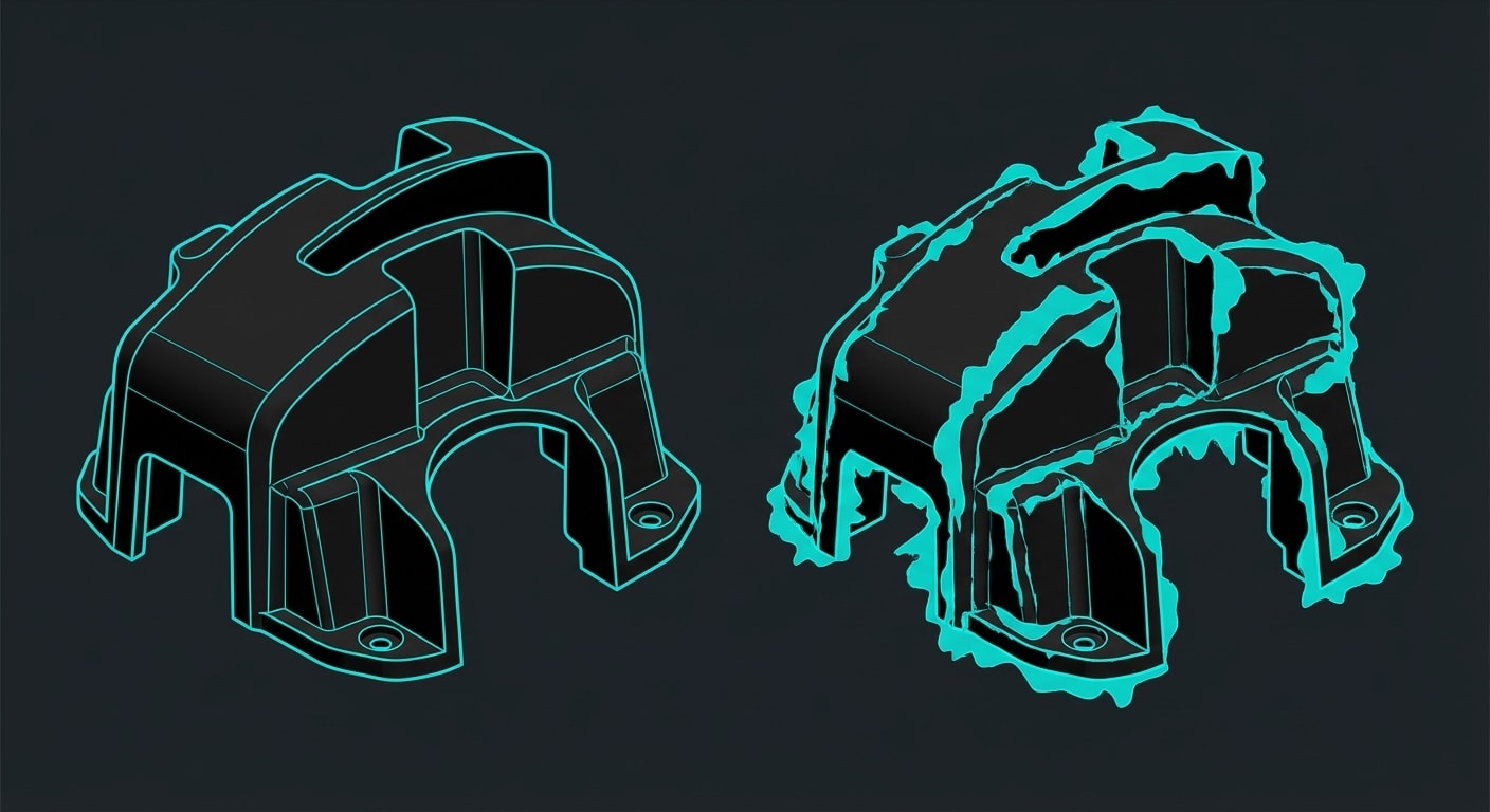
Short Shot
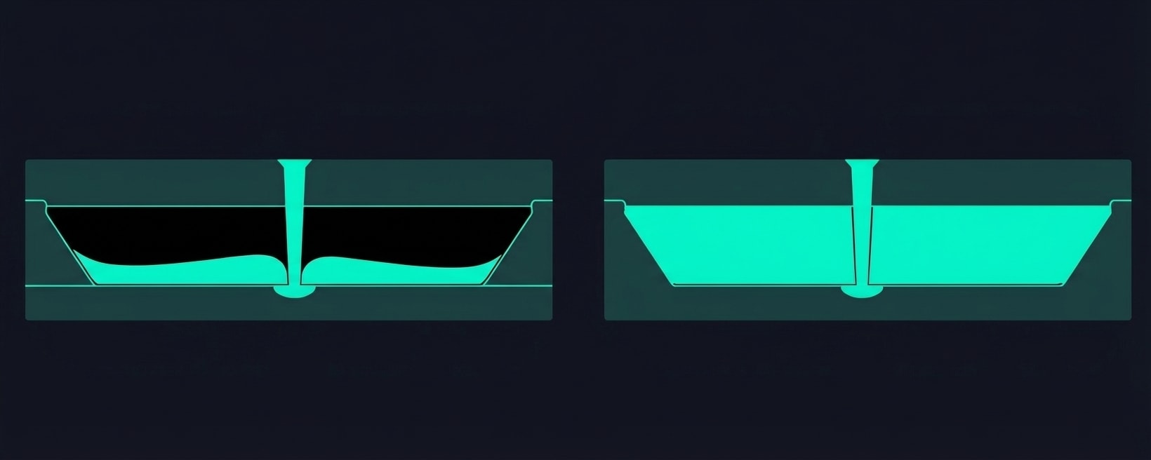 Description: Incomplete filling—part missing sections or features.
Root Cause:
Description: Incomplete filling—part missing sections or features.
Root Cause:
- Insufficient material volume
- Flow resistance too high
- Premature freeze-off
| Category | Action |
|---|---|
| Process | Increase shot size |
| Process | Increase injection speed |
| Process | Increase injection pressure |
| Process | Raise melt temperature |
| Process | Raise mold temperature |
| Tooling | Enlarge gates |
| Tooling | Improve venting |
| Design | Increase wall thickness in thin areas |
Flow Lines
Description: Wavy or streak patterns on the surface, following the flow path. Root Cause: Variations in flow front velocity or temperature during fill. Solutions:| Category | Action |
|---|---|
| Process | Increase injection speed |
| Process | Raise melt temperature |
| Process | Raise mold temperature |
| Tooling | Enlarge gate |
| Tooling | Relocate gate to change flow pattern |


