Runner & Gate Design

Feed System Components
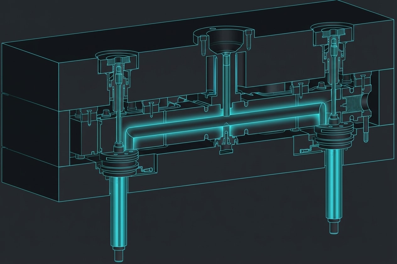
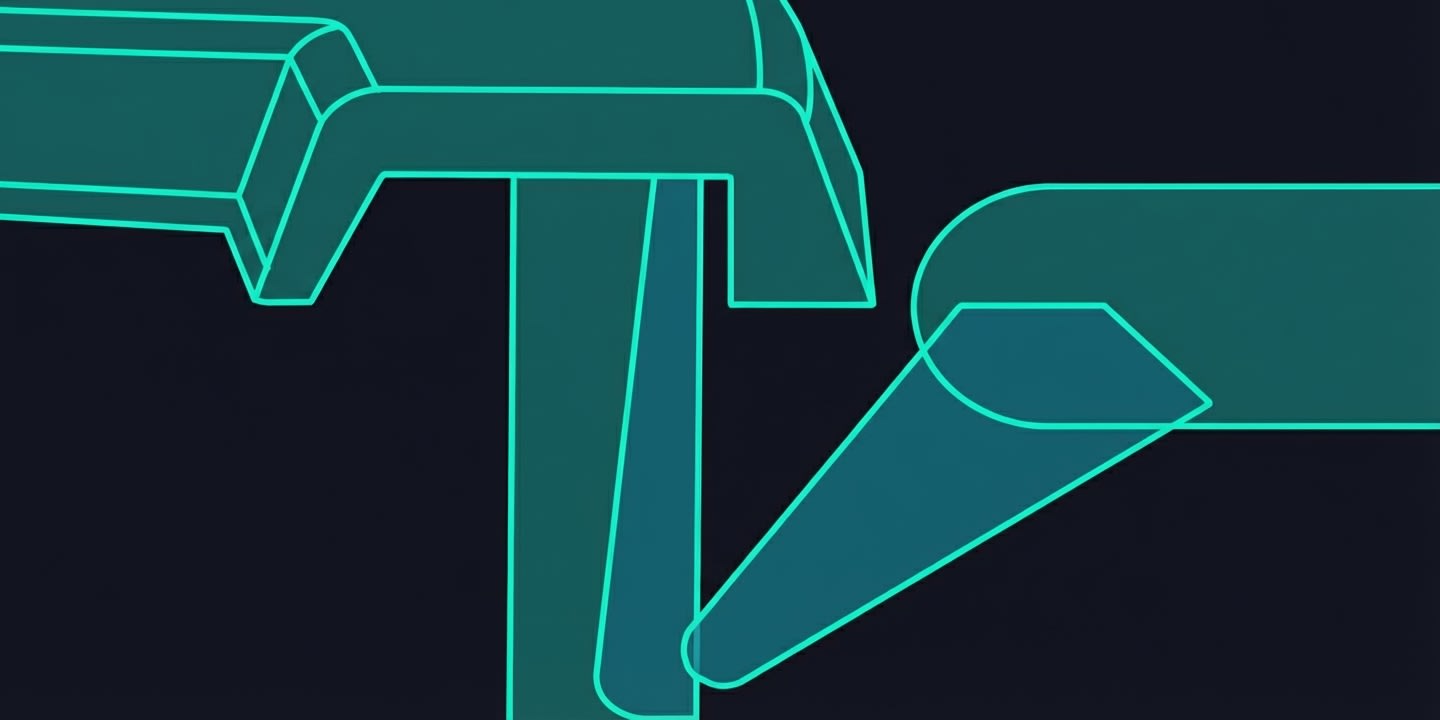
The feed system delivers molten plastic from the machine nozzle to the part cavity:
Nozzle → Sprue → Runner → Gate → Cavity
Each component affects fill balance, cycle time, and material waste.
Sprue
The sprue is the channel connecting the nozzle to the runner system:
Sponsored
April batch closing soon — only 42 seats remaining
Join 3,000+ engineers who got placed at top companies
Design Guidelines:
- Taper: 1-3° included angle (for easy pull-out)
- Diameter: Match nozzle orifice at entry, larger at exit
- Length: As short as possible
- Sprue bushing: Hardened steel insert for wear resistance
Sprue Puller:
A feature in the mold (undercut or Z-pin) that holds the sprue on the ejector side during mold opening.
Runner System Types
Cold Runner
Traditional approach where runners solidify each cycle:
Advantages:
- Simple mold design
- Low initial cost
- Easy color/material changes
Disadvantages:
- Material waste (regrind required)
- Longer cycle time (runner must cool)
- Potential for degraded regrind
Runner Shapes:
| Shape | Efficiency | Ease of Machining |
|---|
| Full round | Best (100%) | Requires both halves |
| Trapezoidal | Good (90%) | One half only |
| Half round | Fair (70%) | One half only |
- Diameter: 4-12 mm typical
- Length: As short as possible
- Balance: Equal path length to all cavities
Hot Runner
Heated manifold keeps plastic molten:
Sponsored
70% of India's auto industry trusts Skill-Lync
For training their engineers in CAD, CAE & simulation
Advantages:
- Zero runner waste
- Faster cycle time
- Better fill balance
- Direct gating possible
Disadvantages:
- High initial cost ($20,000-$100,000+)
- Complex maintenance
- Color changes difficult
- Thermal control critical
Components:
- Manifold: Heated block distributing melt
- Drops: Channels from manifold to gates
- Nozzles: Heated tips at each gate
Gate Types
Edge Gate (Tab Gate)
Entry from the side at parting line:
Characteristics:
- Simple to machine
- Easy to trim
- Leaves visible gate mark
Best for:
- Flat parts
- Prototyping
- Low to medium volume
Fan Gate
Wide, thin gate for uniform flow:
 Characteristics:
- Reduces jetting
- Good for long, flat parts
- More gate trim required
Best for:
- Thin-wall panels
- Parts needing uniform fill
- Fiber-filled materials (maintains orientation)
Tunnel Gate (Submarine Gate)
Angled tunnel below parting line:
Sponsored
Gaurav Jadhav is now a CAE Engineer
Practical projects and mock interviews made the difference
 Characteristics:
- Auto-degating (gate shears on ejection)
- Gate mark on non-cosmetic side
- Limited to flexible materials
Best for:
- High-volume production
- Auto-degating requirement
- Cosmetic top surfaces
Design:
- Entry angle: 30-45°
- Diameter: 0.8-2.5 mm
- Land length: 0.5-1 mm
Pin Gate (Point Gate)
Small circular gate, typically with hot runner:
Characteristics:
- Minimal gate vestige
- Auto-degating
- Requires 3-plate mold (cold runner) or hot runner
Best for:
- Cosmetic parts
- Multi-cavity molds
- Small to medium parts
Valve Gate (Hot Runner)
Hot runner with mechanical shut-off:
Characteristics:
- Best gate quality (no vestige)
- Sequential filling possible
- Highest cost
Best for:
- Premium cosmetic parts
- Large parts (sequential filling)
- Automotive Class A surfaces
Cashew Gate
Curved tunnel gate for underside gating:
Characteristics:
- Gates on non-cosmetic surface
- Complex to machine
- Limited material flexibility
Best for:
- Parts with no side access
- Cosmetic requirements
Gate Location Guidelines
General Rules
- Gate at thickest section — Allows pressure to reach thin areas
- Avoid gating on cosmetic surfaces — Gate mark is visible
- Consider flow length — Maximum L/t ratio depends on material
- Balance flow to all areas — Prevents weld lines, air traps
- Gate away from stress areas — Gate region has high residual stress
Flow Length Limits (L/t Ratio)
| Material | Max L/t |
|---|
| PP | 250-350 |
| ABS | 150-200 |
| PA66 | 150-200 |
| PC | 100-150 |
| PEEK | 80-100 |
Where L = flow length (mm), t = wall thickness (mm)
Gate Sizing
General Formula:
Gate thickness = (50-80%) × wall thickness
Gate width = 1.5-2× gate thickness (for edge gates)
For Tunnel Gates:
Gate diameter = √(4 × part volume / (π × fill time × injection speed))
Typically 0.8-2.5 mm
Multi-Cavity Balancing
For molds with multiple cavities:
Naturally Balanced:
- Runner length equal to all cavities
- "H" pattern or radial layout
- Preferred for critical parts
Artificially Balanced:
- Vary runner diameters to equalize fill
- Uses Moldflow/simulation
- More complex but flexible layout
Key Takeaways
- Cold runners waste material but are simple; hot runners eliminate waste but cost more
- Gate type selection depends on cosmetics, volume, and material
- Gate at the thickest section to allow packing
- Tunnel gates auto-degate; valve gates provide best cosmetics
- Balance runner lengths or diameters for multi-cavity molds
- Gate size: 50-80% of wall thickness
---
Next Lesson: Cooling System Design — the key to cycle time.


