Design for Injection Molding | Injection Molding Fundamentals | Skill-Lync Resources

50% OFF - Ends Soon!

Lesson 8 of 10 15 min

Design for Injection Molding

Overview

Design for Manufacturing (DFM) ensures parts can be efficiently and economically produced. For injection molding, key principles are:

  • Uniform wall thickness
  • Proper draft angles
  • Appropriate ribs and bosses
  • Radii and fillets
  • Avoiding undercuts

Wall Thickness

Uniform Walls
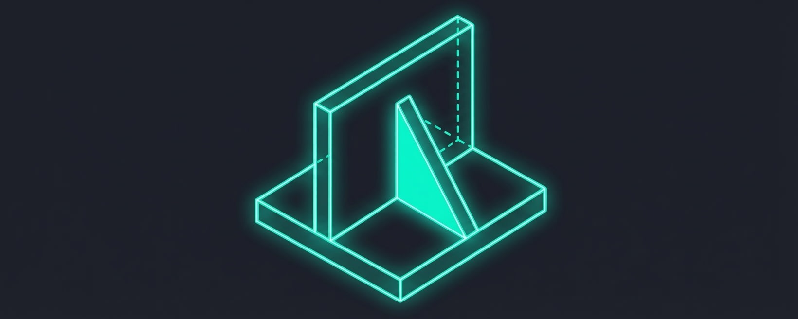
Wall Thickness

The most important DFM rule: maintain uniform wall thickness throughout the part.

Why Uniformity Matters:
  • Uneven cooling causes warpage
  • Thick sections cause sink marks
  • Thick sections extend cycle time
  • Flow imbalances cause weld line issues
Recommended Wall Thickness:
MaterialTypical Range (mm)
PP1.0-3.0
ABS1.5-3.5
PA661.0-3.0
PC1.5-4.0
PEEK1.5-4.5

Transitioning Thickness

When thickness changes are unavoidable:

Sponsored

70% of India's auto industry trusts Skill-Lync

For training their engineers in CAD, CAE & simulation

Learn More
  • Gradual transitions (3:1 slope minimum)
  • Never abrupt steps
  • Locate transitions away from stress areas
Bad: 90° step change Good: Gradual 3:1 taper

Draft Angles

Draft Angle

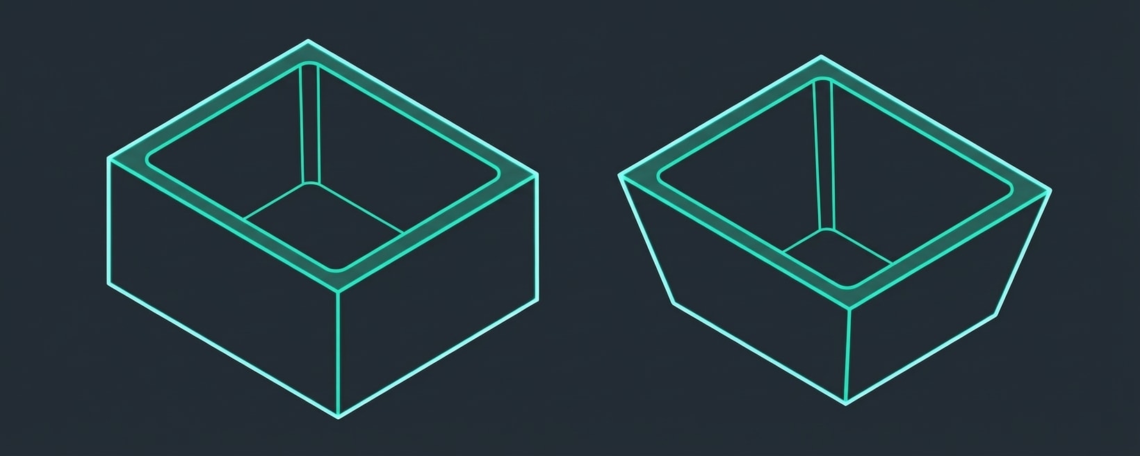
Draft is a slight taper on vertical walls that allows the part to release from the mold.

Why Draft is Needed:
  • Part shrinks onto core during cooling
  • Without draft, ejection force can damage part
  • Vacuum can form between part and mold
Recommended Draft:
SurfaceMinimum Draft
Smooth surfaces0.5-1°
Textured surfaces1-2° + 1° per 0.025mm texture depth
Deep ribs1-2°
Shutoffs3-5°
Rule of Thumb: Add 1° of draft per inch (25mm) of depth, with 0.5° minimum.

Ribs

Rib Design

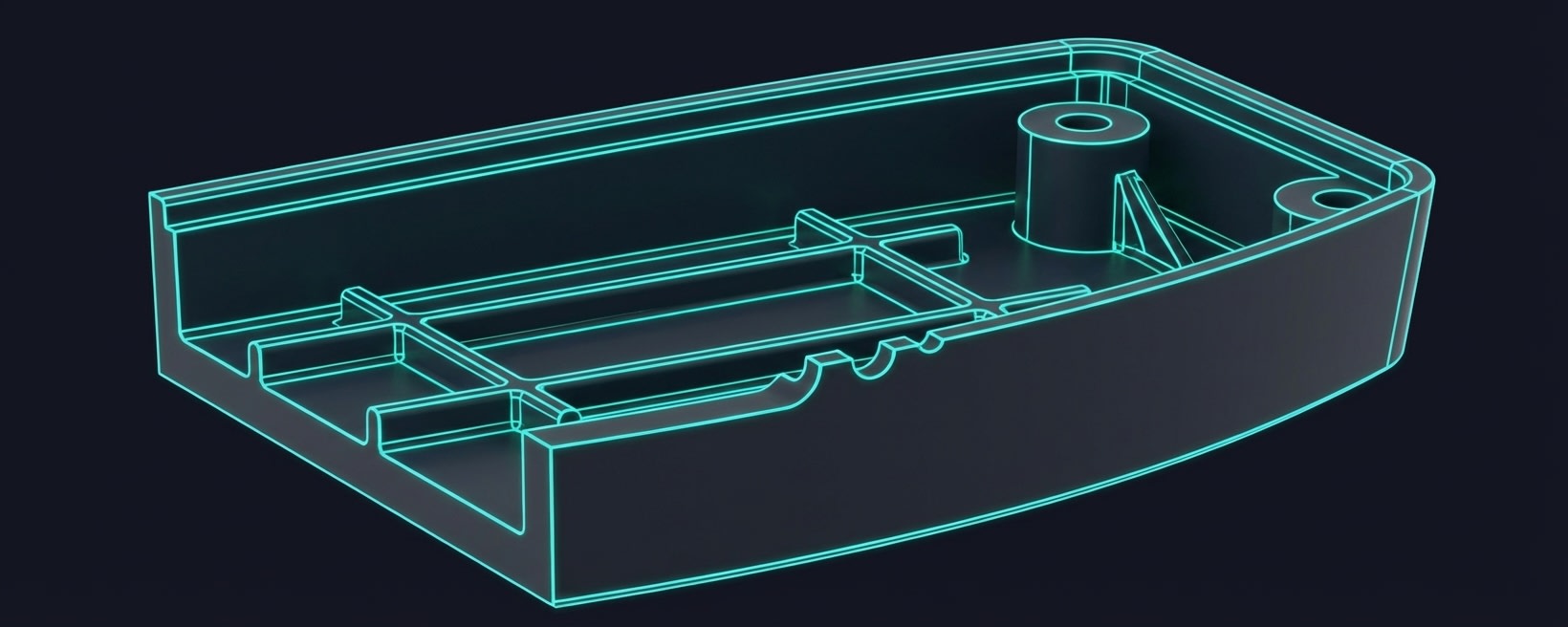
Ribs add stiffness without increasing wall thickness.

Design Guidelines

ParameterGuideline
Thickness50-60% of wall thickness
Height≤3× wall thickness
Draft0.5-1° per side
Base radius0.25-0.5× wall thickness
Spacing≥2× wall thickness apart
Why 50-60% Thickness?
  • Thicker ribs cause sink marks on opposite surface
  • Thinner ribs may not fill properly

Rib Orientation

  • Perpendicular to load for bending resistance
  • Crosshatch pattern for bidirectional stiffness
  • Consider flow direction during fill

Bosses
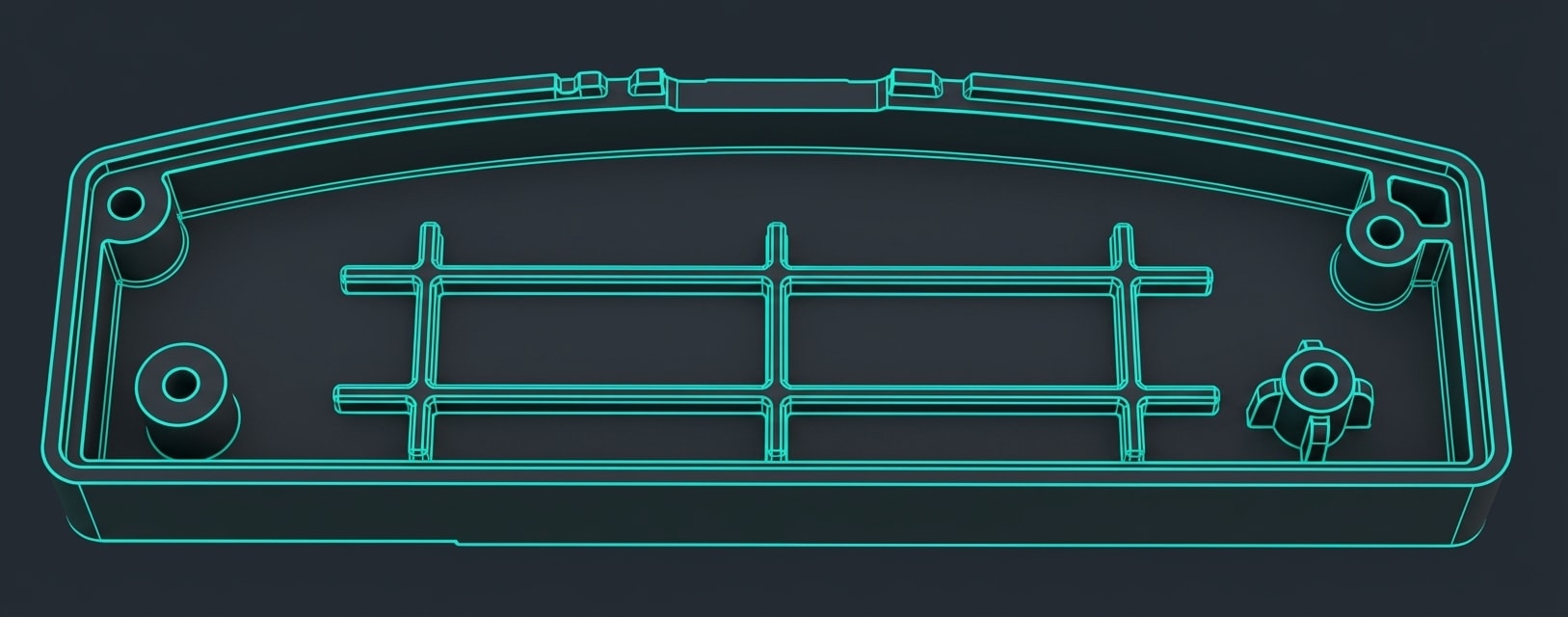
Boss Design

Bosses provide mounting points for screws, pins, or inserts.

Sponsored

Srinithin now works at Xitadel as Design Engineer

Mechanical engineering graduate turned automotive designer

See His Journey

Design Guidelines

ParameterGuideline
OD2-2.5× screw diameter
Wall thickness50-60% of nominal wall
Height≤2.5× OD
Draft0.5° minimum on OD and ID
Base radius0.25× wall minimum

Common Mistakes

Problem: Boss attached directly to wall Solution: Use connecting rib or gusset, not solid connection Problem: Boss wall too thick Solution: Core out to 50-60% of nominal wall Problem: Tall, unsupported boss Solution: Add gussets for stability
🎯 3,000+ Engineers Placed
Sponsored
Harshal Sukenkar

Harshal

Fiat Chrysler

Abhishek

Abhishek

TATA ELXSI

Srinithin

Srinithin

Xitadel

Ranjith

Ranjith

Core Automotive

Gaurav Jadhav

Gaurav

Automotive Company

Bino K Biju

Bino

Design Firm

Aseem Shrivastava

Aseem

EV Company

Puneet

Puneet

Automotive Company

Vishal Kumar

Vishal

EV Startup

Radii and Fillets

Sharp corners create:

  • Stress concentrations (crack initiation)
  • Flow hesitation (incomplete fill)
  • Cooling variations (warpage)

Guidelines

LocationRecommended Radius
Inside corners0.5× wall thickness minimum
Outside cornersInside radius + wall thickness
Rib base0.25-0.5× wall thickness
Boss base0.25× wall minimum
Rule: Inside radius = 0.5× wall, outside radius = 1.5× wall

Undercuts

Features that prevent straight pull from the mold:

Types of Undercuts

  • External undercuts — Protrusions on outside surface
  • Internal undercuts — Cavities or holes inside the part

Solutions

Side Actions (Slides):
  • Mechanical cams move cores perpendicular to mold open
  • Add cost and complexity
  • Require maintenance
Lifters:
  • Angled pins that move during ejection
  • For internal undercuts
  • Limited undercut depth
Collapsible Cores:
  • Cores that collapse inward during ejection
  • For internal threads, deep undercuts
  • High complexity and cost
Stripping (Bump-offs):
  • Part flexes over undercut during ejection
  • Only for flexible materials (PP, PE)
  • Undercut <5% of diameter

Avoid When Possible

Best practice: Design to eliminate undercuts entirely.

Sponsored

April batch closing soon — only 42 seats remaining

Join 3,000+ engineers who got placed at top companies

Reserve Your Seat
Instead OfUse
External snap hookThrough-hole snap (no undercut)
Internal threadThreaded insert (post-mold)
Side holesHoles at parting line

Gate Considerations for Design

Gate location affects:

  • Appearance — Gate mark visible
  • Strength — High stress at gate
  • Fill pattern — Weld line locations
Design Guidelines:
  • Leave flat area for gate
  • Avoid gating on cosmetic surfaces
  • Gate at thickest section
  • Consider flow length to all areas

Parting Line

The line where mold halves meet:

Considerations:
  • Visible witness line on part
  • Flash can occur at parting line
  • Affects draft direction
Guidelines:
  • Place on non-cosmetic surface when possible
  • Design for simple, straight parting line
  • Complex parting lines add tooling cost

DFM Checklist

ItemCheck
Wall thickness uniform?
Thick sections cored out?
Draft on all vertical surfaces?
Ribs ≤60% of wall?
Bosses properly designed?
All corners radiused?
Undercuts eliminated or minimized?
Gate location suitable?
Parting line placement acceptable?

Key Takeaways

  • Uniform wall thickness is the #1 rule—variations cause defects
  • Ribs and bosses: 50-60% of wall thickness to avoid sink marks
  • Draft: 0.5-1° minimum, more for textured surfaces
  • Radius all corners: inside = 0.5×wall, outside = 1.5×wall
  • Avoid undercuts when possible; use slides/lifters when necessary
  • Consider gate location and parting line in early design

---

Next Lesson: Materials Selection — choosing the right plastic for the application.
3,000+ Engineers Placed in Top Companies
Career Growth

3,000+ Engineers Placed in Top Companies

Join the ranks of successful engineers at Bosch, Tata, L&T, and 500+ hiring partners.