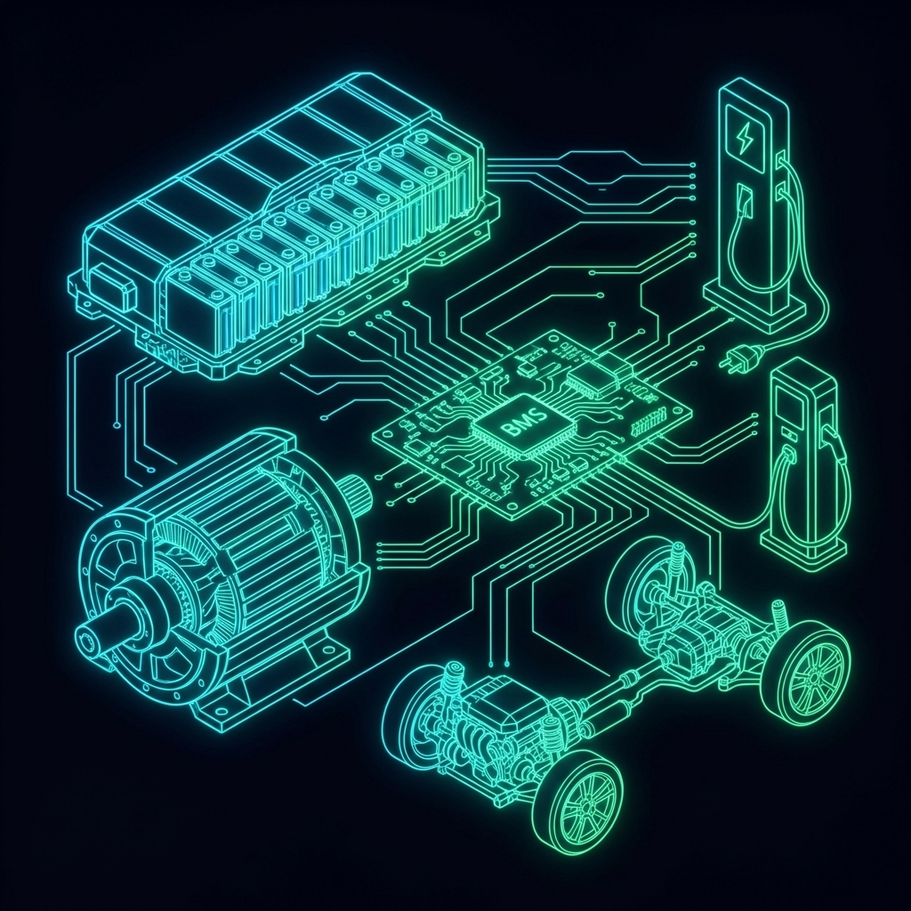
The Battery Management System (BMS) is the electronic brain of an EV battery pack. It monitors every cell, prevents dangerous conditions, estimates state of charge, and ensures the pack operates safely throughout its life.
A well-designed BMS can extend battery life by 2-3× compared to unmanaged charging/discharging.
BMS Functions
Click on BMS blocks to explore their functions. See how data flows from sensors to actuators.
1. Cell Monitoring
Voltage: Each cell monitored to ±2mV accuracy
Temperature: NTC thermistors every 5-10 cells
Current: Hall sensor or shunt resistor (±0.5%)
2. State Estimation
SOC: State of Charge (0-100%)
SOH: State of Health (capacity fade)
SOP: State of Power (available power)
3. Cell Balancing
Equalize cell voltages across the pack
Prevent weakest cell from limiting pack
4. Protection
Over-voltage protection (OVP)
Under-voltage protection (UVP)
Over-temperature protection (OTP)
Over-current protection (OCP)
Short circuit protection
5. Communication
CAN bus to vehicle ECU
Report SOC, warnings, limits
Receive charge/discharge commands
BMS Architecture
Distributed BMS
Module-level slave boards (AFE + MCU)
Master controller aggregates data
Isolated communication between slaves
Common in automotive applications
Centralized BMS
Single board monitors all cells
Simpler, lower cost
Limited scalability
Used in small packs (two-wheelers)
Key IC Components
Component
Function
Example ICs
AFE
Analog Front End - measures voltage, current
BQ76952, LTC6813
Balancing
Cell balancing switches
Internal to AFE
MCU
Processing, algorithms
STM32, S32K
Isolation
Isolate HV from LV
ISO7741, ADUM3160
Contactor
Connect/disconnect pack
HV relay driver
Cell Balancing
Drag cell voltages to create imbalance, then watch passive balancing equalize them.
Why Balancing is Needed
Even cells from the same batch have slight variations:
Sponsored
Get up to ₹60,000 off with Founder's Scholarship
Only 42 seats left for the April batch
Check Eligibility
Manufacturing tolerances (±5% capacity)
Temperature gradients in pack
Self-discharge rate differences
Different aging rates
Without balancing:
Weakest cell hits limits first
Pack capacity = capacity of worst cell
10% cell variation → 10% less usable capacity
Passive Balancing
Method: Discharge high-voltage cells through resistor (waste energy as heat)
From learning simulations to working at an industry leader
See His Journey
Pros:
Simple, low cost
Reliable (no active components)
Easy to implement
Cons:
Energy wasted as heat
Slow (10-100 mA typical)
Only during charging
Implementation:
def passive_balance(cells, threshold=0.02):
    min_v = min(c.voltage for c in cells)
    for cell in cells:
        if cell.voltage - min_v > threshold:
            cell.enable_balance_resistor()
        else:
            cell.disable_balance_resistor()
Active Balancing
Method: Transfer charge from high cells to low cells
Topologies:
Particle cracking: Mechanical stress in active material
Electrolyte decomposition: High temperature exposure
SOH Estimation Methods
1. Capacity fade:
Full charge/discharge cycles
Compare to rated capacity
2. Impedance rise:
Measure DC resistance
Higher impedance = lower SOH
3. Incremental capacity analysis:
dQ/dV peaks shift with aging
Research-grade technique
End of Life Criteria
Application
EOL SOH
Automotive
70-80%
Two-wheeler
60-70%
Stationary storage
60%
CAN Communication
BMS communicates via CAN bus (typical):
Transmitted messages:
Pack SOC, SOH
Max charge/discharge current
Fault codes
Cell voltages (if requested)
Received messages:
Charge enable
Target current
Preconditioning request
Sample CAN frame (simplified):
ID: 0x100 (BMS Status)
Byte 0: SOC (0-100)
Byte 1-2: Pack voltage (0.1V resolution)
Byte 3-4: Pack current (signed, 0.1A)
Byte 5: Max temperature
Byte 6: Fault flags
Byte 7: Balance status
Indian Market BMS
Entry-level (Two-wheelers):
Centralized architecture
8-16 cell monitoring
Passive balancing
Basic protection
Passenger vehicles:
Distributed architecture
96+ cell monitoring
Advanced SOC algorithms
ISO 26262 ASIL-B
Key suppliers:
Indian: Grinntech, ION Energy, Celkon
Global: LG, Panasonic, BYD (integrated)
Key Takeaways
BMS monitors voltage, temperature, current for every cell
Cell balancing equalizes cells to maximize usable capacity
Passive balancing is simple but wastes energy; active is efficient but complex
Protection includes OVP, UVP, OTP, OCP, and short circuit
SOH tracks capacity fade over battery life
Automotive BMS must meet functional safety standards (ISO 26262)
What's Next
In the next lesson, we'll explore Electric Motors — understanding PMSM, induction motors, torque-speed characteristics, and why EVs use motors instead of engines.
Career Growth
3,000+ Engineers Placed in Top Companies
Join the ranks of successful engineers at Bosch, Tata, L&T, and 500+ hiring partners.